Prepare a test scene before the final model
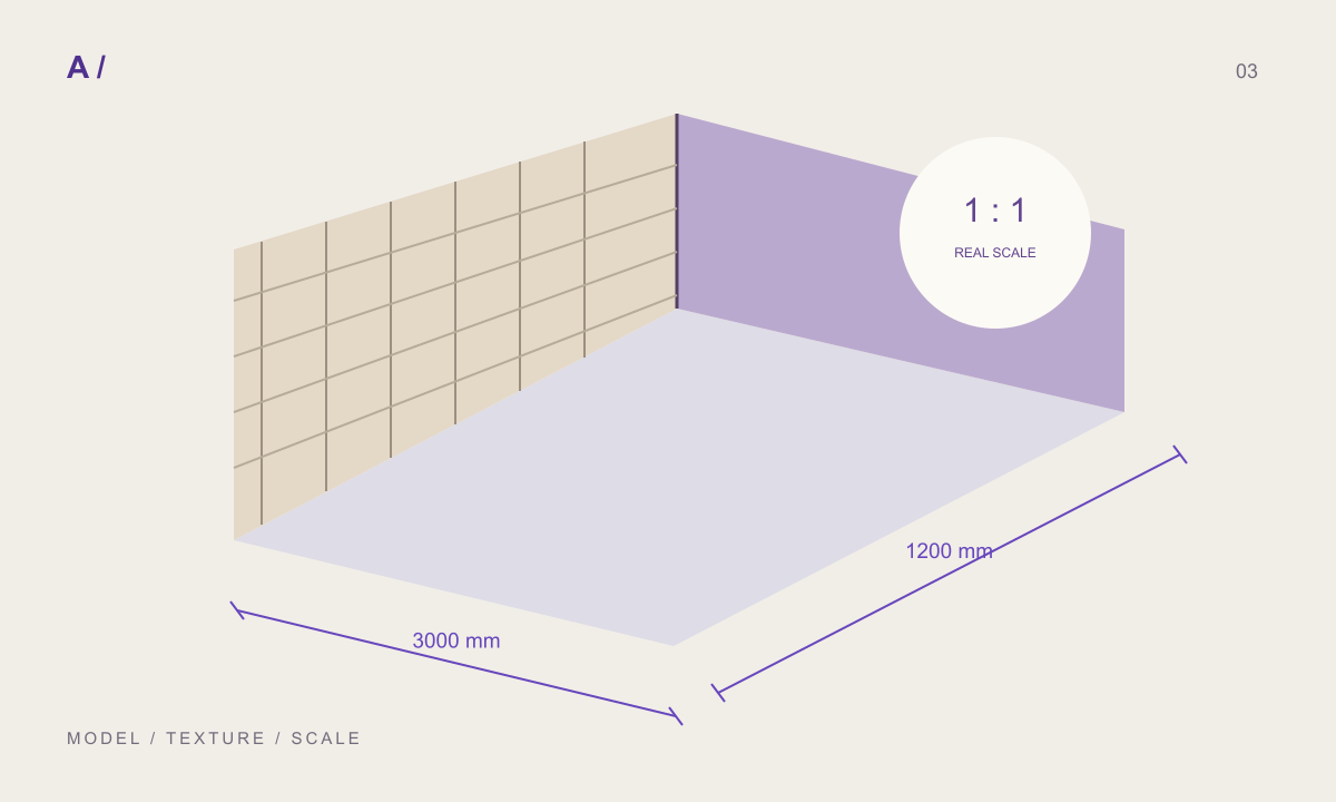
Material setup is easier to judge on a simple object than inside a complete building. Create a plane with known dimensions and keep a second object with a curved surface for reflection checks. Use one consistent lighting arrangement. Name the material after its surface and version, then keep the original package beside the working scene.
This small scene answers several questions independently: does the texture cover the correct area, are all maps aligned and is the apparent relief appropriate? If you change lighting, camera and map strength together, it becomes difficult to tell which adjustment fixed the problem. Save a neutral starting scene for future comparisons.
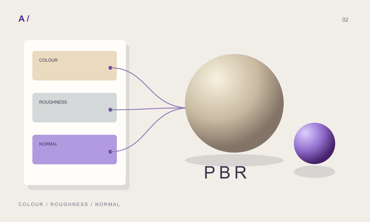
Connect channels according to their meaning
Begin with the colour image and inspect it before adding more maps. Roughness is a separate description of reflection behaviour; a normal image contains encoded direction information. Do not judge a normal map as if its purple-blue colours were a surface photograph.
For a tangent-space normal image, Blender’s documentation specifies a matching UV map and Non-Color image interpretation, with the image connected through a Normal Map node. Keep this technical setup separate from artistic strength adjustments. Once each channel is connected, temporarily disable it and observe the change. This makes swapped files or a disconnected node much easier to spot.
Measure texture coverage on the plane
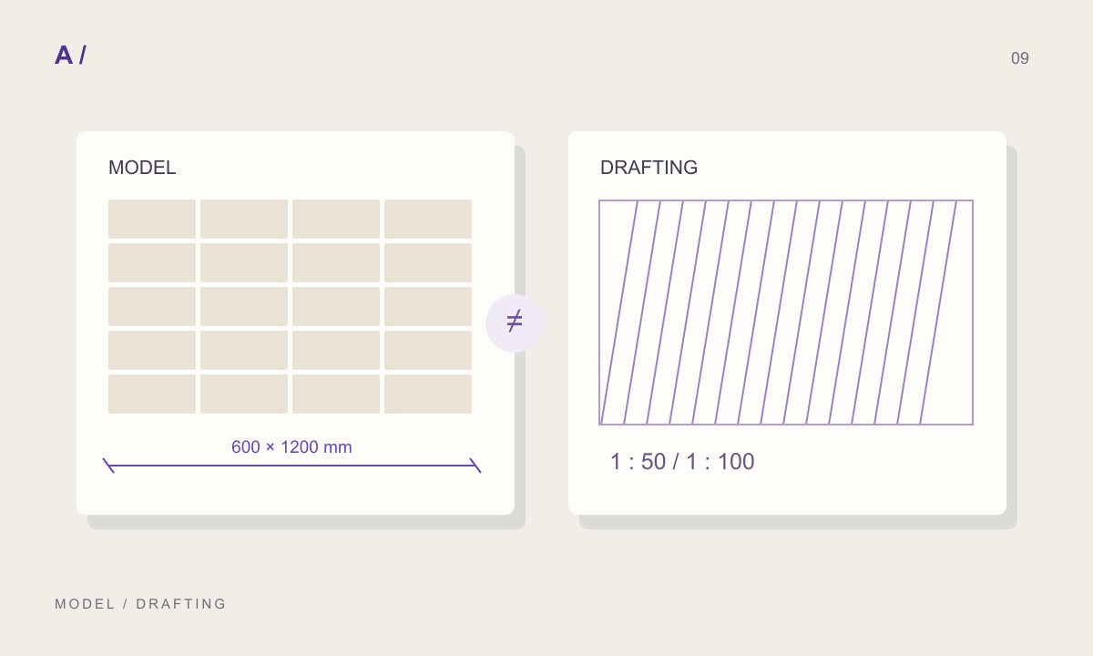
Suppose the complete texture image represents a 2400 × 1200 mm repeat. A plane covering one repeat should be 2.4 × 1.2 metres, not the dimensions of a single slab inside that repeat. If the image contains four smaller units, scaling the whole image to one unit will shrink every joint and surface feature.
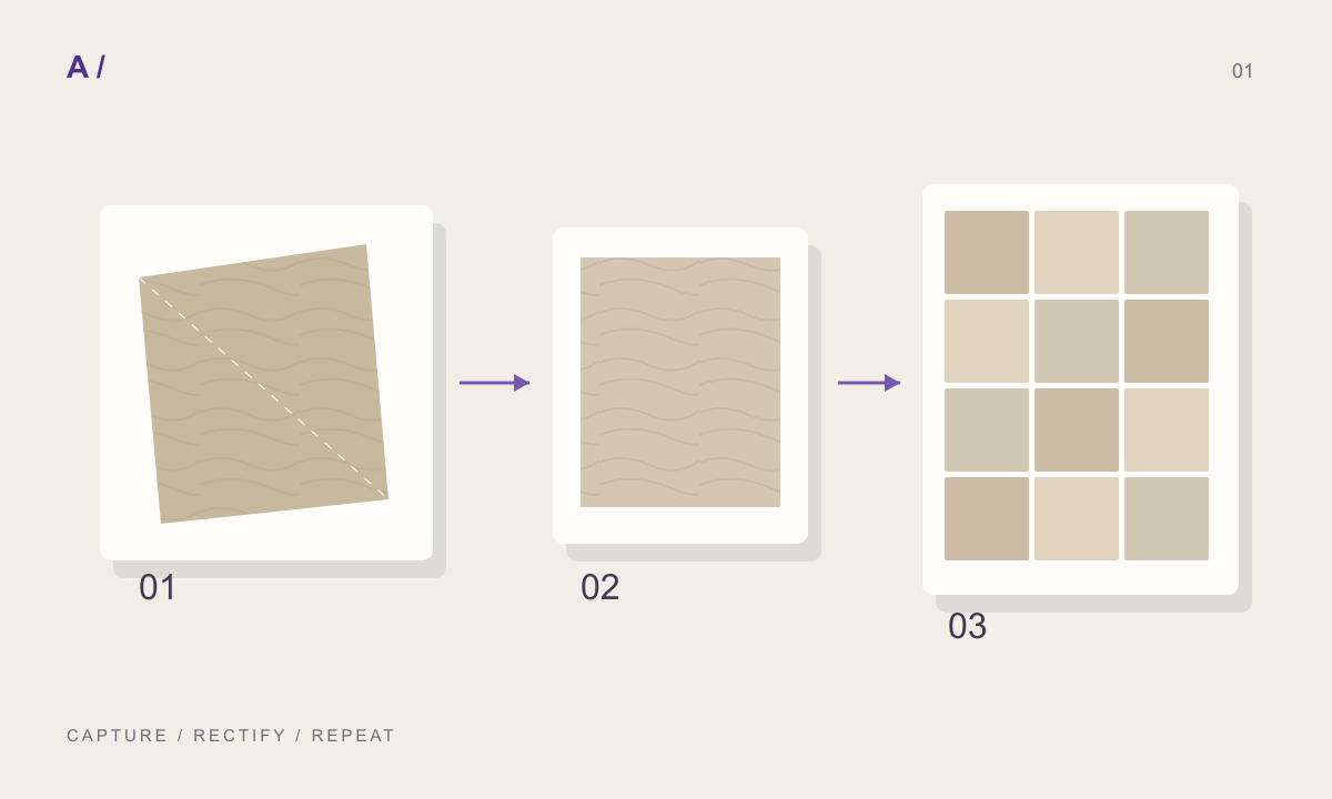
Use a temporary grid or known-size reference to count modules. Check the long direction separately from grain orientation: rotating the colour image without rotating the other maps breaks their relationship. Keep all channels on the same mapping setup unless the material deliberately requires otherwise, and document any exception.
Distinguish shading relief from geometry
A normal or bump effect can make a flat surface appear detailed under light. True displacement changes geometry and requires an appropriate material setup and sufficient mesh detail. Blender distinguishes these methods because they have different accuracy and memory costs.
For a distant stone wall, subtle shading relief may be enough for the intended image. For a close silhouette, actual geometry may matter. Decide from the camera rather than choosing the most expensive method for every material. If the source height was estimated from colour, increasing its strength does not turn it into a measurement. Watch for stains becoming deep holes or raised ridges.
Diagnose one failure at a time
If a material looks flat, check that the intended normal or height connection is active before increasing contrast in the source. If reflection looks too uniform, inspect the roughness input independently. If the colour looks different from the editor preview, compare lighting and colour-management settings before repainting the material.
If pores look inverted, check the normal convention and mapping orientation. Save a screenshot and record the actual change you made. Avoid applying an arbitrary inversion to every future material because it happened to help one package. The useful outcome is a reproducible setup, not a collection of unexplained corrective nodes.
Preserve the shared package and the Blender version
MATERIALHAUS prepares downloadable material files; this workflow imports and sets them up in Blender manually. Retain the original files and save Blender-specific changes in the scene. When the unit size or joint layout changes, generate a consistent new package rather than replacing only the colour map.
For delivery, include the material version, physical repeat dimensions and a test render showing the intended view. Note the Blender version and any displacement setup. Reopen the scene from its delivery location to confirm that textures resolve correctly. A material that looks complete on your workstation can still arrive with missing files on another machine.
Before you hand off
- Colour, roughness and normal files belong to one version.
- Normal-map interpretation and UV mapping were checked.
- A known-size plane confirms physical coverage.
- Relief was assessed at the intended camera distance.
- Texture files resolve after reopening the delivery scene.
Frequently asked questions
Do I need true displacement for every material?
No. Choose according to the required silhouette, camera distance and available resources. A small test makes the trade-off visible.
Does MATERIALHAUS synchronise materials with Blender?
The workflow described here uses downloaded files and manual setup. It does not require a live connection.
References and further reading
Prepared by MATERIALHAUS with AI assistance. Worked dimensions are illustrative; verify construction details and technical product information for your own project.